A functional 3D modeller can be built in fewer than 500 lines of Python by focusing on three core requirements: a data structure to represent the design, a method to display that design on a 2D screen, and a system for user interaction. This approach demonstrates how complex computer-aided design (CAD) tools can be abstracted into manageable components, allowing for the creation of tools that simulate reality without requiring massive codebases.
Core Requirements of CAD Tools
At their core, all CAD tools must fulfill three basic functions: representing a 3D object through a data structure, displaying that object on a 2D screen, and providing a way for users to interact with and modify the design. While domain-specific tools might add features like physics simulations or 3D printing checks, these three pillars remain the foundation of any 3D modelling software.
The challenge in building such a tool lies in managing the complexity of the rendering process while keeping the code size small. By focusing on a specific data structure for the design, the complexity of the rendering logic can be minimized, allowing for a more streamlined implementation.
“However, all CAD tools must include at least the three features discussed above: a data structure to represent the design, the ability to display it to the screen, and a method to interact with the design.”
— 500 Lines or LessA 3D Modeller
Leveraging Legacy OpenGL for Simplicity
The project utilizes Legacy OpenGL, a deprecated but useful graphical API, to maintain a small code footprint. Unlike Modern OpenGL, which requires programmers to write 'shaders' to run on GPUs, Legacy OpenGL provides a 'fixed function pipeline.' This allows the developer to enable or disable automated features like lighting, coloring, and face culling by simply setting global variables.
By using this older standard, the project reduces the amount of linear algebra knowledge required and simplifies the overall code structure. This trade-off is intentional: it sacrifices the high-performance programmable pipeline of modern graphics for the ability to build a functional modeller within a strict 500-line limit.
The Viewer and Transformation Pipeline
The 'Viewer' class serves as the central engine of the application, managing the window creation through the OpenGL Utility Toolkit (GLUT) and driving the main rendering loop. It handles the transformation pipeline, which converts points from 'model space' (the object's local coordinates) to 'world space,' and finally to 'viewport space' (the 2D screen coordinates).
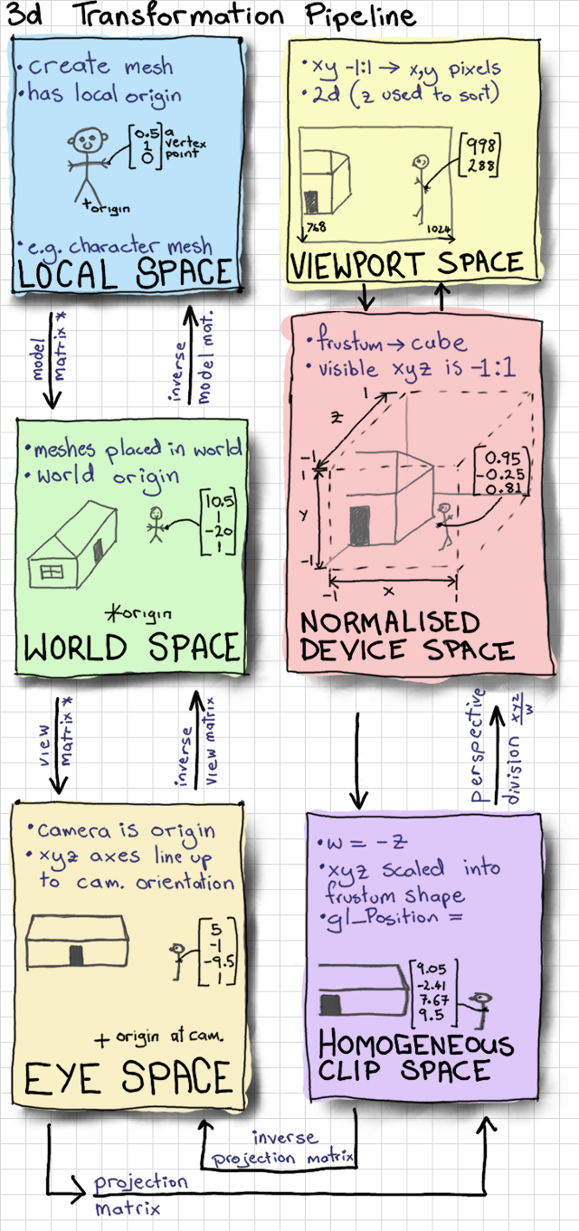
This figure illustrates the transformation pipeline managed by the Viewer class to convert model space to viewport space.
The Viewer initializes the OpenGL state, including the projection matrix and light sources, before calling the Scene's render function. It also manages the 'ModelView' matrix, which combines the object's position in the world with the viewer's perspective to determine what the user actually sees.
Scene Abstraction and Limitations
The 'Scene' class provides the primary interface for the 3D design, abstracting away the underlying data structure. It maintains a list of 'nodes'—the individual components of the 3D model—and tracks which item is currently selected by the user. This separation allows the rendering logic to remain consistent regardless of how complex the individual objects become.

The Scene class maintains a list of nodes, which are organized into a specific hierarchy of subclasses.
While this 500-line approach successfully establishes a functional 3D modeller, it has inherent limitations. Because it relies on Legacy OpenGL, it cannot easily implement the advanced, programmable effects found in modern 3D engines. Additionally, the provided source material does not detail the specific implementation of the 'Interaction' class or the full hierarchy of 'Node' subclasses.

This image provides a visual example of a sample scene rendered by the 3D modeller.