The creator sought to combine a fluid simulation with audible feedback by implementing a FLIP (Fluid Implicit Particle) algorithm on an electromechanical flipdot display, motivated by the pun 'FLIP fluid on Flip Dots' and the desire to hear the swishing sound of moving fluid that silent LED‑based simulations lacked. Panels were obtained from Sam, aka Look Mum No Computer, who maintains a museum of obsolete technology and donated a stock of old flipdot displays, some dating from 2007, after commercial panels proved prohibitively expensive—often requiring budgets exceeding $50,000 from the sole remaining manufacturer. The 13×28‑pixel arrays, manufactured in groups of seven dots, were earmarked for an installation at the EMF2026 event.
Each flipdot changes state in about 60 ms with a millisecond‑long pulse, but the original panel’s wiring required scanning columns one at a time, resulting in a full‑frame update of roughly one second. To overcome this bottleneck, the creator adopted a colleague’s design of soldering a custom driver circuit onto the rear of the existing PCB, using low‑cost H‑bridge motor‑controller chips (e.g., MX6208) to drive each dot directly. This required cutting the column traces to prevent electrical interference while leaving the row connections intact thanks to built‑in diodes, and it allowed grounding one pin of each dot so that column lines could be tied to ground, simplifying the wiring. The H‑bridge chips are SOIC‑8 parts rated for 0.5 A continuous, controlled by 8‑bit shift registers that directly set the A and B inputs.
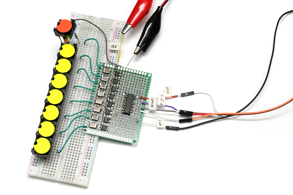
This image illustrates the custom driver circuit using low‑cost H‑bridge chips and shift registers that enabled direct control of each flipdot, overcoming the panel’s slow native scan‑based update.
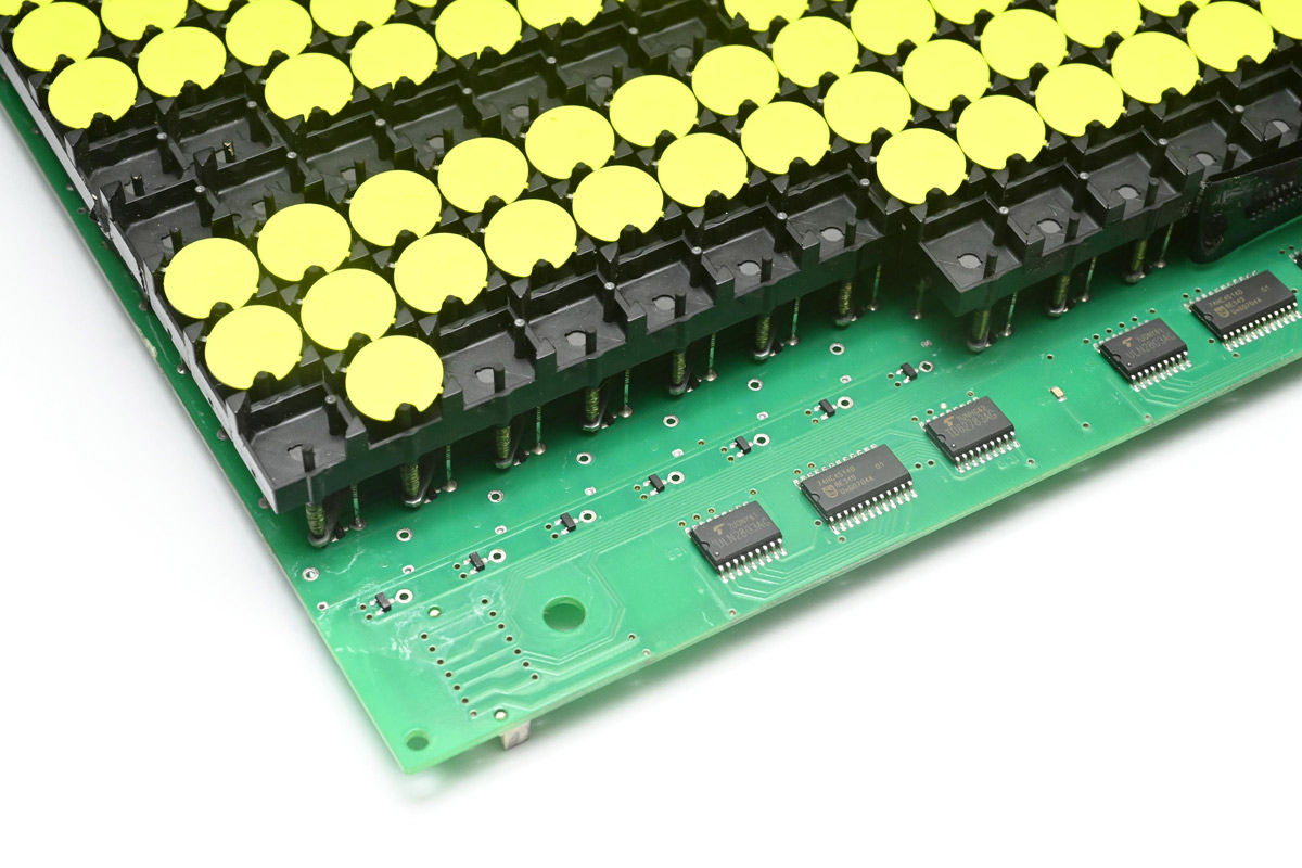
The visible diodes confirm the design choice to preserve row connections while cutting column traces, allowing the H‑bridge circuit to drive columns directly via ground.
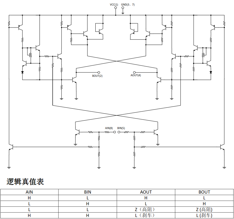
This schematic shows the internal configuration of the H‑bridge chip that was controlled by 8‑bit shift registers to set the A and B inputs, enabling precise control of each flipdot.
Although the H‑bridge approach promised theoretical update speeds as low as 56 ms by pulsing all relevant rows simultaneously, practical limits emerged: the coils’ 18 Ω resistance demands about 666 mA at 12 V per coil, scaling to several amps for the full panel, and any residual synchronization errors across the matrix would produce visible artifacts. Alternative ideas such as capacitor‑based half‑bridges or gate drivers were considered but rejected due to excessive cost, complexity, or risk of component failure. Despite these constraints, the completed installation demonstrated a working fluid simulation on the flipdot display at EMF2026, marrying computational fluid dynamics with the distinctive auditory and tactile feedback of electromechanical pixels.