Jane Street’s blog post explains that the ASIC puzzle handed participants the final GDS layout of a small chip and asked them to determine its function without a netlist or internal signal names. The chip is a hardware checker for an 11×11 Star Battle puzzle, also known as “Two Not Touch”. It accepts 121 cycles of binary inputs, each indicating whether to place a star in the corresponding square. Internally, the design runs parallel checks: a 2‑bit counter for each row and column requiring exactly two stars, a 121‑bit ROM that maps squares to coloured regions together with a 2‑bit counter per region (also requiring two stars), a delay line that ensures no two stars touch—even diagonally—and a total‑star counter used for Easter‑egg outputs. All checks are ANDed to produce a success signal. When success is asserted, the output generator emits a solution string. The strings are stored in ROM but are obfuscated with a small LFSR driven by the game board; solving the puzzle requires deobfuscating the string. Most incorrect attempts yield the message “TRY AGAIN”, while certain incorrect boards trigger Easter‑egg messages. These include a 57×57 pixel Jane Street logo formed by about 1,400 isolated metal‑2 squares, the Morse code “PER ARENAM AD ASTRA” (through the sand, to the stars) etched in an unused layer, and a floating‑wire bug in the “TWO NOT TOUCH” path that causes the output to appear as “TWO”
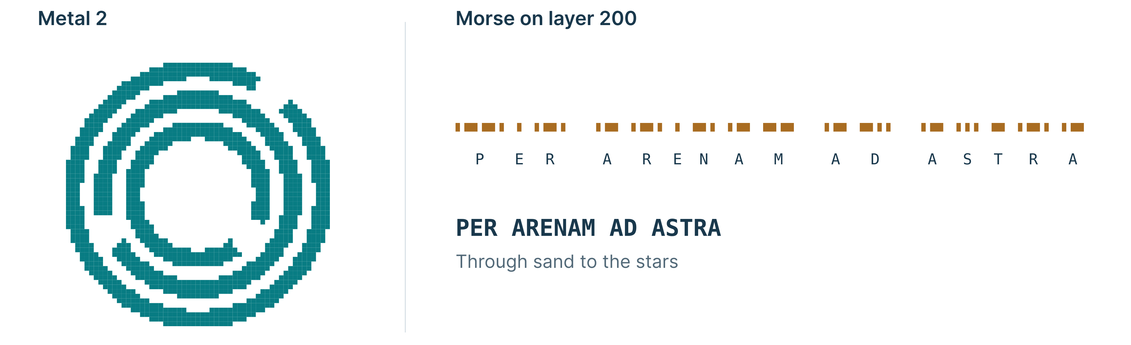
The article describes that incorrect boards trigger Easter‑egg messages, including a 57×57 pixel Jane Street logo made of about 1,400 isolated metal‑2 squares and the Morse code “PER ARENAM AD ASTRA” etched in an unused layer.

When success is asserted, the output generator emits a solution string stored in ROM but obfuscated with a small LFSR driven by the game board; solving requires deobfuscation. Most incorrect attempts yield “TRY AGAIN”, while certain incorrect boards trigger Easter‑egg messages.
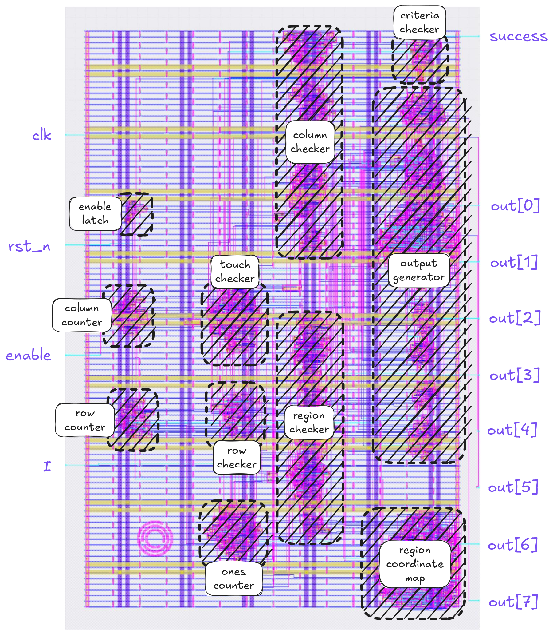
Internally, the design runs parallel checks: a 2‑bit counter for each row and column requiring exactly two stars, a 121‑bit ROM that maps squares to coloured regions together with a 2‑bit counter per region, a delay line that ensures no two stars touch—even diagonally—and a total‑star counter used for Easter‑egg outputs.
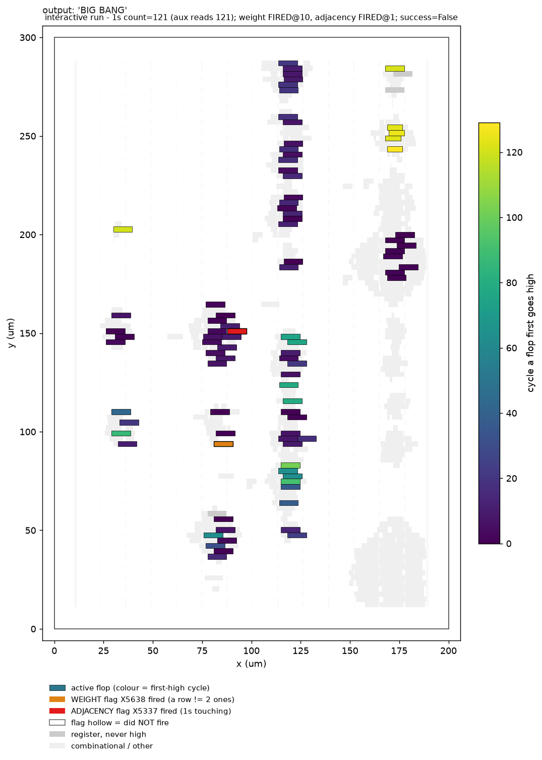
The chip accepts 121 cycles of binary inputs; internally it runs parallel checks including row/column counters and a delay line preventing diagonal adjacency.