A camera in a 3D scene is not magic: it repeatedly changes how a point is described. In the simplest camera-relative case, a point `(x, y, z)` becomes `(x/z, y/z)` on screen. If `y` means up and `z` means forward, increasing `z` shrinks both screen coordinates, so objects appear to approach the vanishing point. For example, `(2, 1, 2)` projects to `(1, 0.5)`, while `(2, 1, 8)` projects to `(0.25, 0.125)`. That is the “divide by depth” shortcut behind the interactive examples in Gabriel Oc's article.

The animation supports the opening explanation that increasing camera depth moves projected screen positions toward a common vanishing point.
The shortcut is also a special case of a perspective projection matrix. A full pipeline first moves a point from shared world space into camera-centered view space, then multiplies it by a 4×4 matrix to produce clip-space coordinates. Dividing those coordinates by their `w` component yields normalized device coordinates (NDC), which describe position inside the camera's visible bounds before mapping to pixels. When focal scale and aspect ratio are both `1`, the matrix's `x` and `y` formulas reduce exactly to `x/z` and `y/z`.
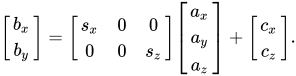
The equation gives a visual counterpart to the discussion of projection matrices, clip-space coordinates, and normalized device coordinates.
The extra coordinate answers a practical question: why use four numbers for a 3D point? The source explains that `(x, y, z, 1)` preserves the original point while allowing a 4×4 matrix to operate on it. It also distinguishes a point from a direction, represented with `w = 0`, which is unaffected by translation. The broader pipeline matters because real cameras also need direction, position, field of view, aspect ratio, and near and far clipping planes; the simple depth division omits those concerns.

The formula illustrates the fuller camera pipeline that accounts for camera position and orientation before projection and clipping.
This is an educational demonstration, not a complete rendering system. The author calls the examples constrained and naive, and says practical 3D work usually needs the fuller projection machinery. The supplied Wikipedia page independently frames 3D projection as a technique for displaying a 3D object on a 2D plane, while the Phosphor3D repository shows why skipping clipping, culling, and careful depth handling can produce distortion or incorrect drawing order. The central lesson is narrower but useful: depth division reveals the perspective step; a camera adds the surrounding transformations needed to make that step reliable.